Procedural Grass Generator with Houdini

General / 13 August 2018

While i am working at Lighthouse VFX Studio , we were making our grasses using Softimage and Maya setup. After that we decided to make our grass setup in Houdini. So after working about it couple days i have created this grass setup. So, i can share with you guys if anyone need a setup like that.


This is the project like: Houdini Procedural Grass Setup


- This setup is all procedural and so easy to change little things. File2 node ( i dont know why i didnt change the name lol) is input geometry data. After that i am scaling geometry to 0.01 because of geometry is very big and i like to play with small number. So... I am making three part of geometry. 

1- Grass area

2- Play area ( all animation's area , that will change for each episode or project)

3- Road area


Ok first i am calculating the distance which i will use this first and taking output . 


Remeshing the geometry then transformed it on Y direction and scaled 0.999 , 1, 0.999 just because it worked better when i do this. I dont know why lol So after that i used ray sop to ray it to the original geometry ground and grouped them so this way i had a data for only the edge of the geometry. Because i will use that point data for point cloud to create border data


I have calculated distance before and created maxdist data also using point cloud. With this VOP SOP i am using distance and maxdist data for creating color to create a border for the geometry. My color ramp is between white and black and with this method, i am creating all-white geometry with a black border
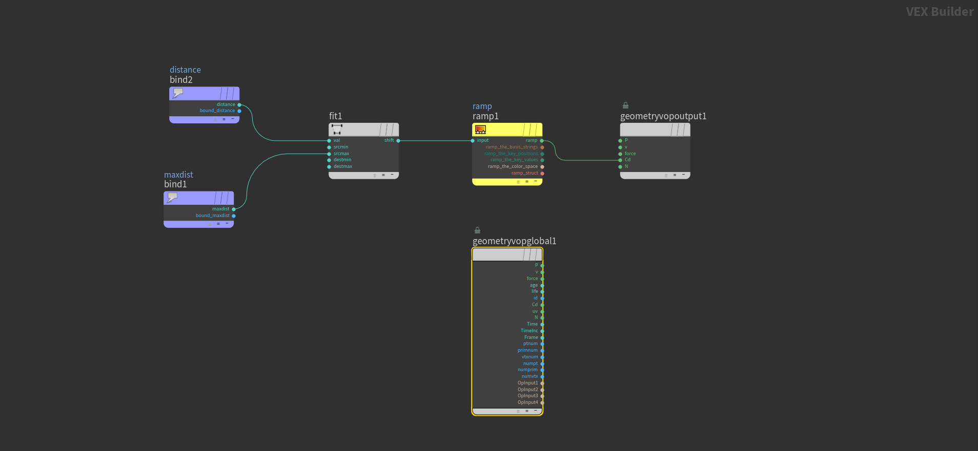


Attribute blur after point cloud


This is a point cloud example for creating a color gradient. With this method, i am taking data from the road and with point cloud data giving a gradient color to the geometry which is creating white color as long as closer to the road and color getting gray and dark as long as the camera gets far from the geometry.

   WHY?

Because this method is better optimization for Rendering. If grass closes the road there will be a higher density of the grass and far parts will have a lower density of the grass. This way grass geometry mesh will be lighter and also while rendering the grass it will be faster because of far distance will be in DOF and nobody will understand if there is a less amount of grass or high.


So, I deleted the geometry into two parts. Small_High_Group part is deleted by playground area which i have separated on the first image. So, this part will be a higher amount of the point scatter. And Group_for_Lower_Part will be very far apart and created another group on Big_High_Part. This part will have a high amount of the scatter point also.

Merged two parts of scattering and gave them a color randomly in VOP SOP between 1 to 0.75 and i used that color data for scale.y. This will give randomize scale differences between 1 and 0.75 which will make the more natural look. 

On Grass_Color_Turbulance VOP i have created two types of turbulence color. So, i am giving one big color turbulence and one small color turbulence and mixing them each other. With this method i will have a good blend of turbulence and will use it for color and scale difference also
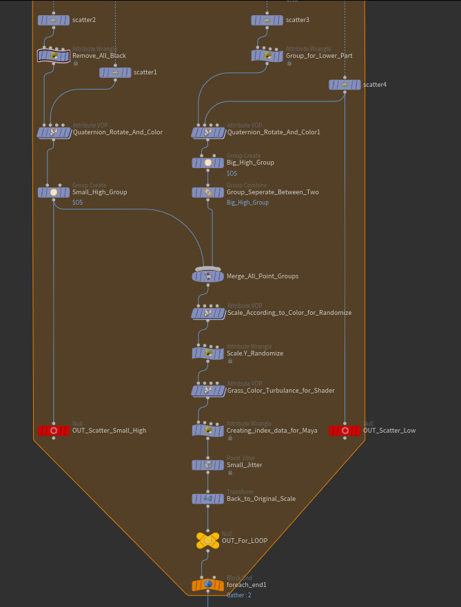


Ok this is the key point actually and hard to explain also. Basically i have created random orient data here. Because i want to have rotate data in point scatter. I will export this data to Maya and will instance there so this way i must have all data in point scatter. This one is creating orient data which mean is 4 vector data


And these are for MAYA actually. Just using color turbulence data, pscale data and orient data then converting them for Maya. Like Pscale to RadiusPP , Orient to RotationPP etc...


And this is the last result of the grass setup in Houdini viewport. If the grass is close to the road they are very small and low density on the edge of the road and grasses which is far apart to the road has higher. There is a color turbulence as you can see and light color grasses are the longer than darker color area   


Thank you 

Report

Houdini Procedural Transformation

General / 19 July 2018

I was watching Entegma's Low Poly Transform tutorial and this idea come up on my mind.

For Entagma's video here is the link: Entagma Low Poly Transform

My Store Link: Houdini Procedural Poly Transfrom


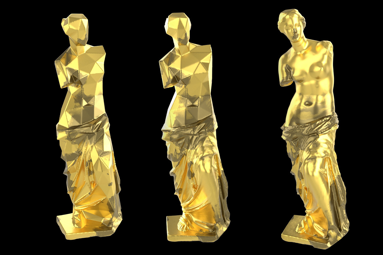
This is the reasult of morphing setup


I have used high-res geometry and used polyreduce node to make it low poly version


This picture shows the color mask, i just gave simple color mask but if we want we can make it noise color map too. This color map comes to VDB from Polygons node with extra attribute i created on point.mask name. Gave it mask VDB Name and ready to use that data


Simple Instance lighting setup


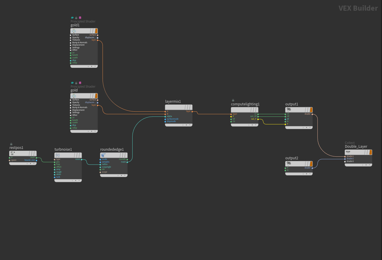
I have added two color of shader. Open color gold and darker color of gold. I feed them to layer mix and otherside restpos taking the position data for shader and gave it tubulent noise to create noise for the shader. Rounded edge use that noise for the edges only and you can me something old look. After that feed the rounded edge to layer mix's alpha connection. Compute light node is necessarly use. There are two output connect to collect because of i have sahder but should feed the displacement too. This way output2 (on the bottom) is giving dispalcemnt data which is 0

For better check: Houdini Procedural Materiel


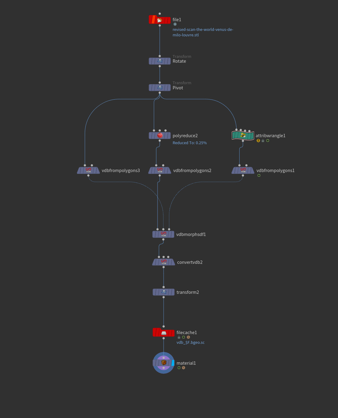
This is my basic workflow. I use original geometry and using polyreduce node to make it lowest poly. With attribwrangle1 i am creating color data using

" f@mask = chramp("ramp",relbbox(0, @P));
@Cd.x = @mask;" code

This VEX code creates color ramp data on the geometry with ramp slider. I gave animation to ramp slider for morph. You can give noise ramp colro data also. 

vdbfrompolygon3 is original high-res geometry

vdbfrompolygon2 is low poly geometry

vdbfrompolygon1 is ramped geometry

I connect three of them to vdbmorphsdf and played with Timestep , actually just made it two lol after that converted to polygon and cached that heavy data to see faster animation.


  Than you

Report

Houdini Procedural Parquet Setup

General / 10 July 2018

Store: https://www.artstation.com/sercan/store/Le7/houdini-procedural-parquete-setup


  I was working for interior design and built this parquet setup. That was fun to work and discover something like that.


Firt of i have created a box and made two groups. First group rotate 45 degree to left , second group rotates 45 degree to right. This was i could create parqute pattern. After that i deleted top of the box and allign the rest to the ground 0 posiiton.

if(@P.y < 0.1){ 

    removepoint(geoself(),@ptnum)

}

This code , deletes everything over 0.1 on Y position 

and P.y = 0; is alling everything to 0 poisiton on Y position

After that i used transform node to make it on the center point and than clipped on every way like Left, Right, Up and Down to have perfect square shape for pattern. This way it will be all procedural and we can copy the grid if we want.

Other way for bigger places we can build bigger grid and different scatter count.


After clipping i have pack them and gave random colour to points with attribvop. I fed the turbulent noise with P and multiply it with original Position and connect that to color ramp and Cd out. With this method i can use one shading and color differences will make texture different color look. Black parquets will be darker texture color and this way texture will look more natural


I used group range node to select few parquets to bend. Deleted rest and keep small ranged points.

This is how i gave different Poisition and Break parts to parquets. After color varation is done i unpacked them and used for loop to give them more division. With bend node i calculated each parquet's center position and bended from the center. Small parts will ben less than the longer parts. After that i gave random expressions to Taper so that way they will turn and twist different way from each other. I used int(fit11(random($PT),-3,3) So, this gave them minus and positive 3 unit taper for each parquet according to thier point number and multiply it random number.

To the main parquete i have small turbulent noise to Y Position. This way ground level will have small differences.


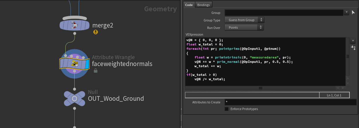
This small VEX Code is calculating face weight normals.


After everything is done, i made another for loop and polyextured grid parquets and facet normals. Gave them uv texture in loop because of i wanted to give almost same uv to each parquets and this way material could work better. With color differences texture look more natural. I just forgot to give us to side of the wood so that way they look so fake from the side lol IF you use this method dont forget to give them uv from the side also


Thank you

Report

Procedural Animation & Camera Projection

General / 03 July 2018


I was working on a project and couple point were very little bit challenging so i have decided to share them, maybe some one need that part or might be someone can not solve that for their project and find this article lol 


OK, the main idea was there is a rail system and boxes transferin with small holder via rail. 

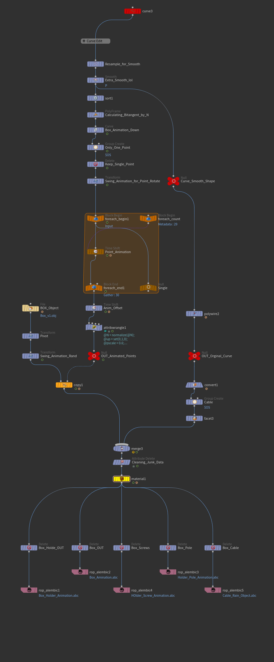
I have created a rail first. Created basic curve and shape it through the art director's directions on the scene. That was the most challenging part actually :) i had many revised for shaping of the rail system. So , anyway... After rail curve is done! i sort them , first (0) point was on the top and the last point close to the ground. Added poly frame for calculating N through curve long like the image on below. I usded Poly Frame to calculate N like this becasue easy and fast also cheap method.


I added Carve node to give an animation to curve and deleted rest of the points but 0 one! Thats the key actually. I need only the one point for animaiton and taking that animatin data from my main curve. If i get another revised from the director about the curve. ıt will change the animation automaticly when i edit my curve. And also gave little bit random swing to my point. Actually it is just a rotation.

I usded fit11(rand($FF*5),-10,10) this gives rotation between -10 and 10 , 5 times on sin which means 5 swing on total frame 


OK, This is how i multiplied my animated point 30 times in a row. I used for loop and got the iteration data for timeshift node. I added like $F-detail(-1"iteration",0) * ch("Random")

OK this is taking the iteration data and multiply it with the chanel that i created on Random name which 30 times. So this gives me 30 points animation and iteration number from the loop will give me timeoffset. 

For example if my iteration number is 10 , that will give me 10frame timeoffset for each points. Which will make first point on time , second point will start 10 frames later, third point will start 20 frames later, fourth point will start 30 frames later bla bla bla...


So this is how i project the video footage to meshes on the scene! Well meshes has uv actually but that uv doesnt work with the video footage. I added uvtexture node and selected Cameara input as a texture type. This method creates uv from the camera view and work very good actually. I have use it many times, one of my favorit also lol


And this is how uv looks after projecting from the Camera


After changed/arranged uv , i added materiel node and created simple, basic , easiest material and added video footage as sequance jpg


This is how i arrange uv texture and materiel also


This is how it looks after i projected uv to the mesh and added the video footage to meshes also. I deleted some parts becasue of i didnt need them like ground , boxes or so. I kept like this becasue of some boxes were going back side of the small tower. I didnt want to roto/mask them while comositing, I adjust that small tower's mesh as close as the video but still needed some roto while compositing


On this picture there are projected meshes and video footage also. So, i combined them both to show how it looks


Total workflow , easy and simple scene for this project. For render , our rendering department didnt want me to export all file in one so i exported them the way they want lol


Report

Procedural Growth Points & Lag With Solver

General / 29 June 2018


I needed a growth system for a project then i changed it little bit to achive this kind of effect. 

On the first picture i am showing how to create a growth system using with solver sop. First ı have created a growth system then i used that color data for lag system. Actually lag became soooo much easier than i thought lol i will tell you about that too. But first how i created the growth system.


OK, first of all i usded test object lol. As you can see on the picture i scattered points from surface, so other option is you can use iso offset to fill the geometry and this way you can scatter point inside the object too. anyway... I scattered points from the surface and used wrangle "f@grow=0" or scattered points and "f@grow=1" for group points. I used few spheres for group points but you can select by hand or random numbers also. After that merged both numbers and feed to solver.


On here , this is inside the solver.  I added a attribute wrange for solver codes. So, basicly i am calculating ner points and converting if grow data is 0, make it 1 and continue like that. This way my points will move with solver becasue of feeding from the previous frame.


So, This was the most easy and simple VEX code i have ever used i think lol So, i merged previous frame and first input together. Ok, Solver Sop taking data from the previous frame and adding it the current frame. This way when we do or change a data it will effect the data on next frame. This way i thought like if i multiply the color with some number , color will fade away during other frames and that happened. 

@Cd.r *= 0.015;   This code multiply the color with 0.015 for each frame and this way red color will disappear few frames later. I did few test for the number and found correct number for my setup


And this is my simple workflow for this setup. Basicly i scatter points from the surface and select few emitter points with group. After that giving a data name called "grow" 0 and 1 to points. Scattered point's grow data is 0 , group points' data is 1. With Grow Solver i am transfering 1 data to 0 and changing grow data from scattered points. After that deleting everything but grow 1 data and using another Solver on Lag Solver name. With that solver i am multiplying my red color data until it get all black. With few test i found correct number to multiply and Red data gets all Black after 10-15 frames. 

Then i used that data for particle sim but i have lost my file after sim is done. This way couldnt share the pop network here. All i can say is that was very very simple sim data. I just emitted from points, added turbulance and drag thats it lol. 


Thank you so much.......

Report

Houdini Debris and Rotation by Distance

General / 13 June 2018

I have created this setup while working on a project. Debris setup is basic actually but i want to show something different which we say secondary animation after sim is done. Using first and the last frames of the animation and calculating distance, which that data giving rotation to the geometry for each centers.


First of all i painted some edges for debris points, group the red parts and delete the rest

for group: 

if(@Cd.r < 0){

     i@group_Redgroup=1;

 }


For simulation setup actually it is very basic particle setup. I gave pop wind and drag , drag has a ramp according to age and that let me control the drag the way i want to give drag force with the ramp. I have used original geometry's velocity data as force with fieldforce. So, i used sopgeo to import animated geometry data to dop network and connect it with fieldforce and used data as veloctiy. This method for using animation's velocity data as force and this way force will be in the network as long as animation and also fast moves strong force , slow moves will be light force as a wind or force


After simulation is done we needed secondary animation as a rotation, this way i used this method and created new data named "way". I used first and the last frames of the animation and calculated each one's lenght and then divded from each other. After that calculated the distance between first and the last position. That distance calculate for each geometry and creats "way" data for each geometry.


Using "way" data calcualted matrix and gave some rotation using VEX. With this method we can give rotation on x,y,z directions and i multiplied them 90 degree because of my distance data were very small and i had to have to multiply them with big numbers. If your "way" / distance data is big numbers , you dont need to multiply it with big numbers or you might need multiply like *0.5 , *0.1 or so.


Report

Houdini Cloth With Grain Solver

General / 06 June 2018


Every Houdini user knows that , Cloth is pain in the a$$ in the Houdini. Because its very heavy and expensive to use. Cloth is heavy because using single CPU and honest has a GPU support. This way I have discovered another way for cloth using Grain Solver which is multi-thread and also GPU support.


Normally what we do for cloth sim in Houdini? We do cloth sim in low poly mesh, then use cloth capture node from first frame and then use cloth deform node for deforming points and sometimes it can be little bit a problem if you need high res mesh sim like running character or character that makes fast moves. 

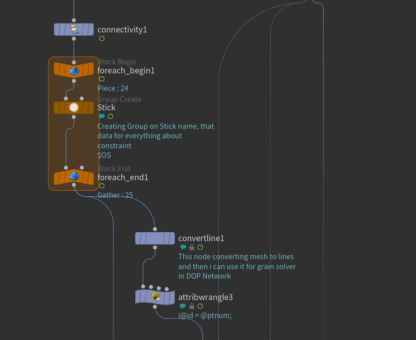
In here i subdivided mesh which kills cloth normally but work well here with Grain solver. So, I had many flags and used same flag for all. I used foreach loop for group and selected top of the flag with Stick group. I will use that group for all my sim until it finish. After grouping top of flags I used convertline node , that node converts mesh to lines using primnum. After that I used attribute wrangle and gave id to points using i@id = @ptnum;  


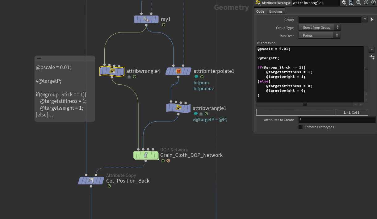
This part is little bit tricky because I used ray node for constraint! So, I used object merge and took animation data to my geometry. On the left side I connect Cloth object and on the right side of the RAY  I connect Constraint object and select minimum points. After that I connect Ray to attribinterpolate node for taking the animation and also used hit prim and hit prim uv data with Attrib Interpolate node. On the left side I used attribwrangle for creating upscale , target position and used if loop about target stiffness and weight with following codes.


 @pscale = 0.01;

v@targetP;

if(@group_Stick == 1){

       @targetstiffness = 1;

       @targetweight = 1;

}else{

      @targetstiffness = 0;

     @targetweight = 0;

}


With these codes I created couple data and that data I will use inside the DOP Network. Basically I have created my stick group's stiffness and weight is 1 and this way it will constraint to target poisition form right side connection of the Ray node


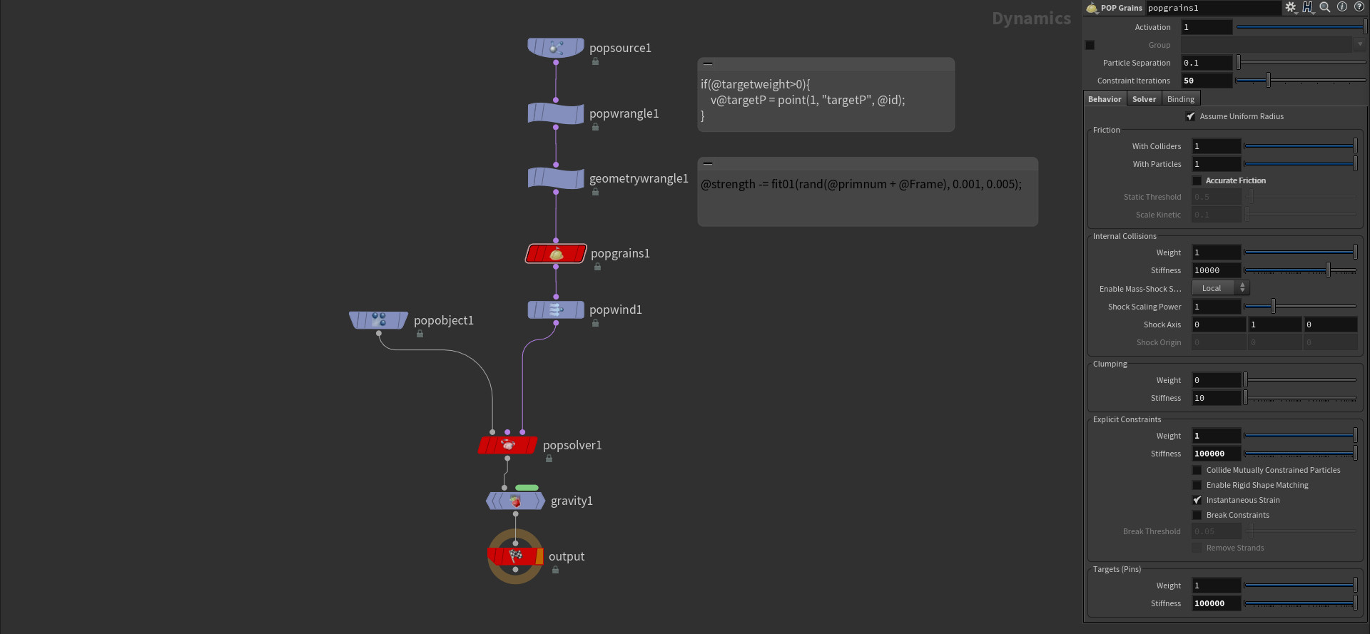
This is inside of the DOP Network... I used pop sour to generate my cloth object as a particle for 1 frame and first frame only $SF==1 and used pop wrangle for connect points to target position

if(@targetweight>0){

    v@targetP = point(1, "targetP", @id;

}

This code will connect and constraint point to animated object

and also used geometry wrangle @strength = fit01(rand(@primnum + @frame),0.001,0.005);

This code will add strength each frame and will be randomly between 0.001 and 0.005 because of my scene scale. You can change them numbers.


And this is the workflow of the Grain Cloth Sim Setup. After sim is done with DOP Network we  will be seeing mesh with converted lines so to get a original geometry back, we can use attribution copy and select Position data for points. When we we select that our flag geometry will take the original geometry back and will copy animated Position data to it.


Thank you.....


Report

Houdini Procedural Wrinkle With Tension Map

General / 30 May 2018


It is another easy method to create wrinkle using VOP SOP and Turbulance

First , i had to have to rig this tube becasue of this easy animation lol after rig captured i added RestPosition node to get rest position. After that i added measure node to calculate the area and i will use that are to create deform data inside the VOP. After that i have added another measure node with area_deform attribute.


In this VOP i feed import primitive attribute with primnum. There are two primitive attribute i am taking inisde the VOP. Thet are "area" and "area_deformed" that i have just created outside of the VOP and subtract them from each other. Then i fit them and promoted paramater to outside with "Intensity" name. That will create the destination of MAX and used bind export wtih "tension" attribute. One more thing before leaving the VOP is CD data becasue of i want to see how much distance that i am gonna use.


Second VOP for creating turbulant noise using rest and tension data. 

On the first VOP i craeted "tension" data using area datas so now i am using import point attribute this time and feed them with ptnum from geometry global. I am using turbulent noise and feeding it with rest's poisition data and multiplying it with tension data. This way i am creating a setup that effects only the tension data. So if tension is 1 it will be white color and if there is no tension it will be 0 data which make it black. White parts of the geometry will effect from turbulent noise and can create the wrinkle or some sort of noise that we pick. After that i use diplcement node and feed the amounth with multplied data. Constant is for color data , i dont wanna see that black/white parts.


Ok this is how it look like after subdividing. Picture on the up is showing us tension data. White parts will be effected by turbulent noise from second VOP and black parts will stay the same and will not effect by anything. This is very easy way to create fake wrinkles or some animated effect like that.


This is the workflow about this easy setup... I can not add the file here but i can share if anybody need that hip file. 

Thank you.

Report

Houdini Procedural Material with Material Builder

General / 21 May 2018

check it out from www.sidefx.com too


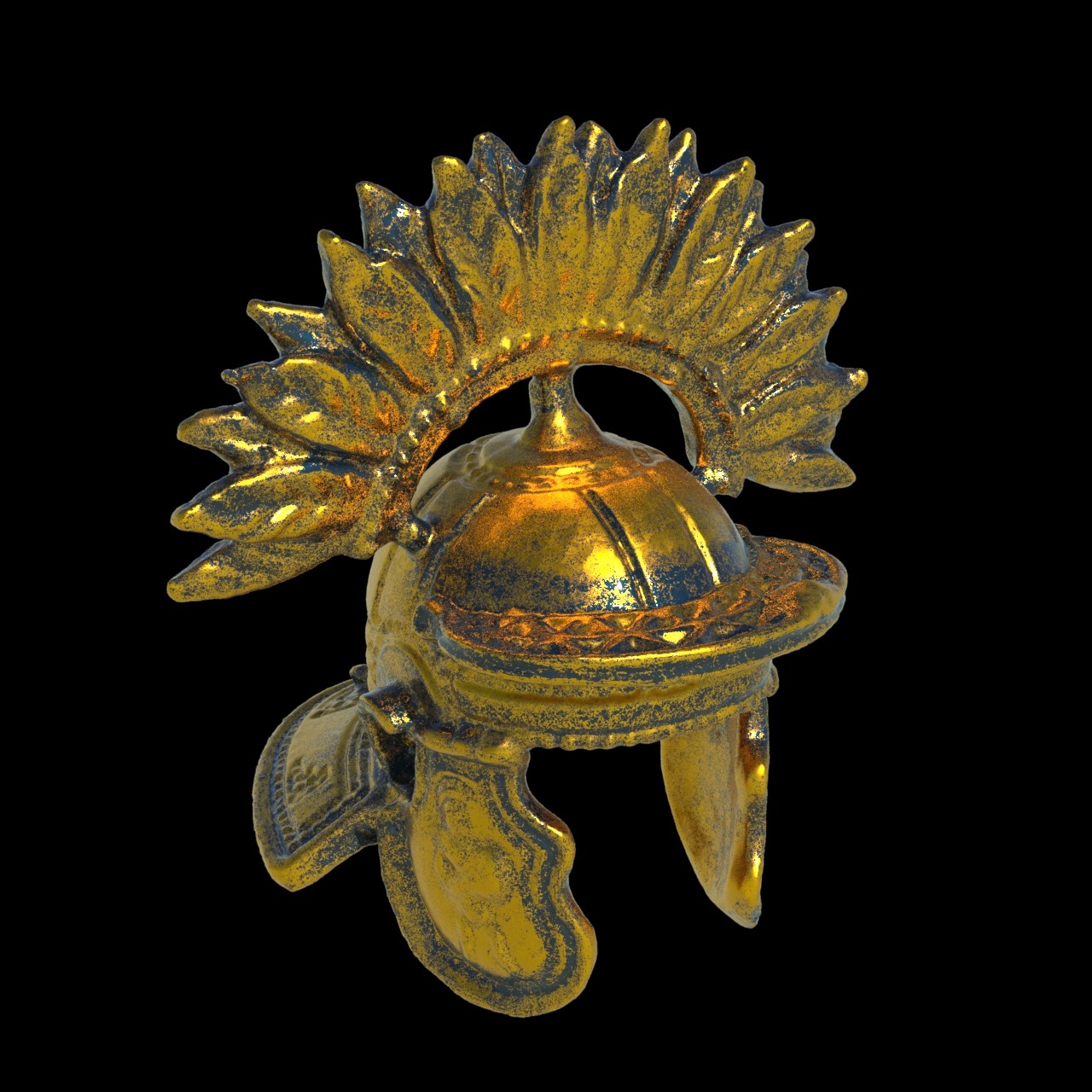
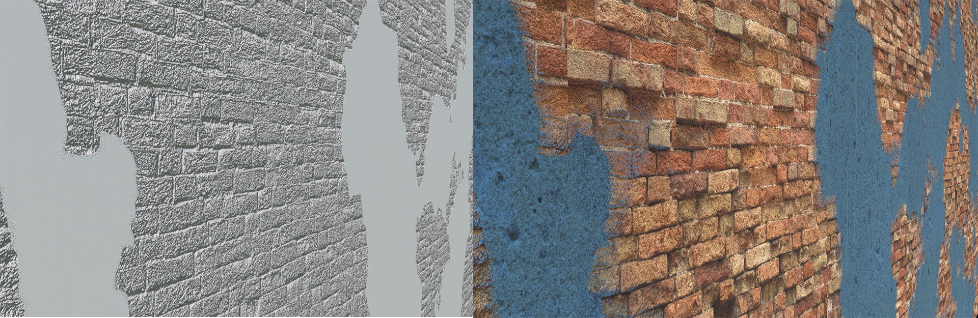
I was playing with Houdini materials and were doing R&D , discovered very easy material setup that we can create material that look used, old, can add rust or anything to our creativity. There are few renders that i can show how it look like.


There is setup on the ground, very easy , simple , easy to use.


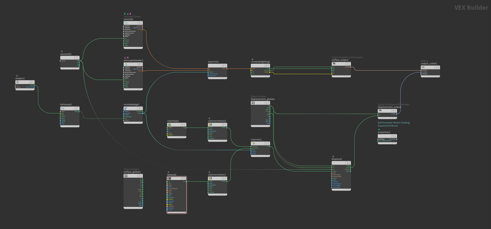
First of all there are two different materials we need. I picked car paint and brushed metal shaders to combine. There is a mix layer sop that mix two different layers to each other or we can use more layer mix to mix many layers to each other or create a material the way we wanna see. On layer mix sop there is alpha setion , so that section is kind of trick because that section let us to set our mix. 

I have used rounded edge sop to select edges and radius it with Turbulent noise and played little bit with my noise. For noise we should use Rest position sop also. On same method we can play with Discplament also.  

After layer mix node we should add Compute Lighthing node and connect layers to it and geve all feed to Cf , Of and F which Channels, Color,  Alpha and then we can output it. I have used parameters for Noise becasuse of i wanted to try if i can make it timelapse. Just becuase we can not key frame it inside the VEX Builder, we should use parameters to give a keyframe animation.


For displacement i needed to add couple more nodes to achive my result. First of all i comped shader1 and shader2 mix out in Houdini and used that map for displacementtexture node. Then connect Position and Normal outs to displacement output and connect that to collect. BUT, when you render like that , you will not achive the clean result. 

After trying few more things i discovered another thing for clean result. I added properties node and conect that to Output Collect. For properties node click Edit Parameters from Parametes section and enabled Discplacement Bound from Render Properties / Mantra / Shading section. And Displacement Bound should be 1 , so it comes 0 as a default and dont forget to change it. With this method you can have all procedural shader with procedural displacement also and useful with game engines. But for game engines dont forget to Bake texture first.


Thank you for reading my blog...

Report

Spring Constraint for Leaves or Multiple Object

General / 03 May 2018


 While the time working about Environment modeling we have discovered new way to give wind or noise to leaves using rigid body dynamix. It is pretty fast and also useful method becasue of working with any kind of force in Dop Network. This system can effect from pyro or flip fluid and also if you give too much power to your force/wind, your leaves will be tearing from the constraint and will fly in the air with your force.


This is workflow of the setup. Pretty easy and fast actually. 

- I had an setup for Tree or Bush creating which i posted that blog before lol you can create your tree on procedural way with l-system or you can use the tree from speed tree or polygon modelled mesh and so. Bush imput is only points for leaves , leaf input is my leaf that i modeled in Houdini also. Coppied them to points and packed them , then deleted all geometry but points. Gave them an id and used that points for my constraints.

First input for Leaves and the second imput is for my constraint points that i will use in the DOP Network. You can see the DOP Setup inside of it


First i have used rbdpackedobject node to get all packed leaves. Pop speed limit is for limiting the maximum speed , so i limited it for 5 because of it was ok for my scene. There are two different force so there is popwrangle force @torque = curlnoise(@P+@Time*2)*200; that creates torque inside the DOP which works like popwind or fanforce and the second force is popwind. I just put two of them to show there are different kind of force that we can use and also we can use any kind of force with multisolver.

There are two springconrel. One is controling the poisition and the other one controling the root group that i have created out of the DOP. I have it VEX codes too. and constraint network connect them to my setup. First input of the constraint network feeding by the rbdsolver and second input feeling by the springconrels , so i changed SOP Path of constraint Network as a 1 input (which houdini starts from 0) this way SOP Path taking data from my pos and rot data that i have created out of the DOP


Report